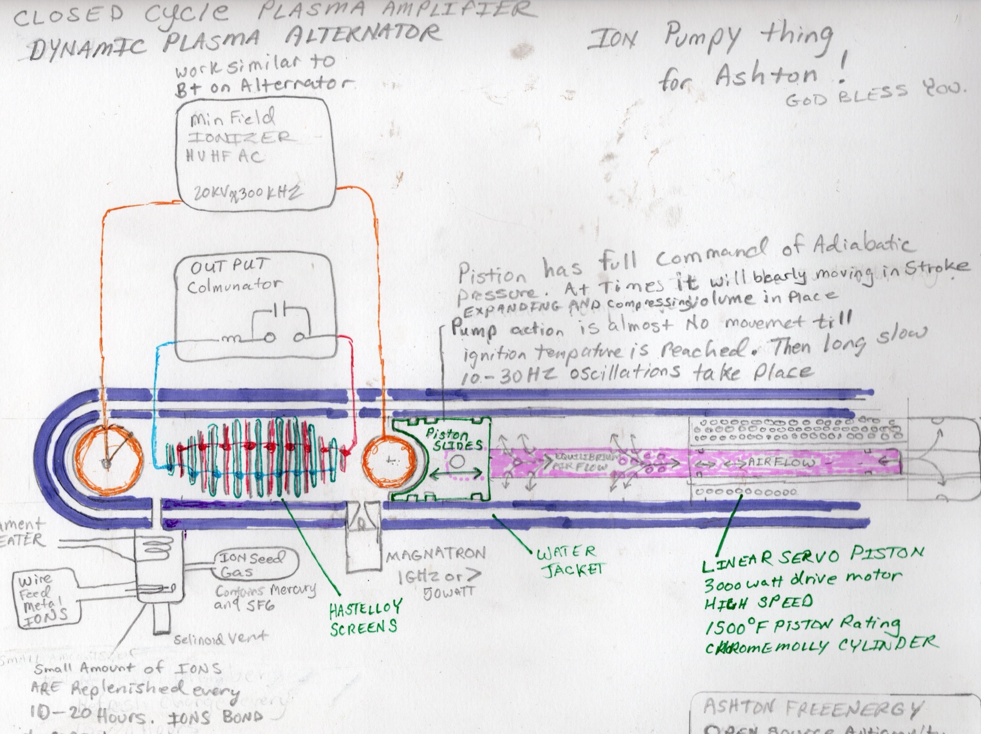
CLOSED Cycle PLASMA AMPLIFIER
DYNAMIC PLASMA ALTERNATORtitle as written on the sheet
DYNAMIC PLASMA ALTERNATORtitle as written on the sheet
Ion Pumpy Thing and its family · 3D reconstruction v2
Seeded plasmafast hot electrons · slow heavy ions
Outputsealed bench form: screens → coil + capacitor → arc · vehicle form: plasma envelope
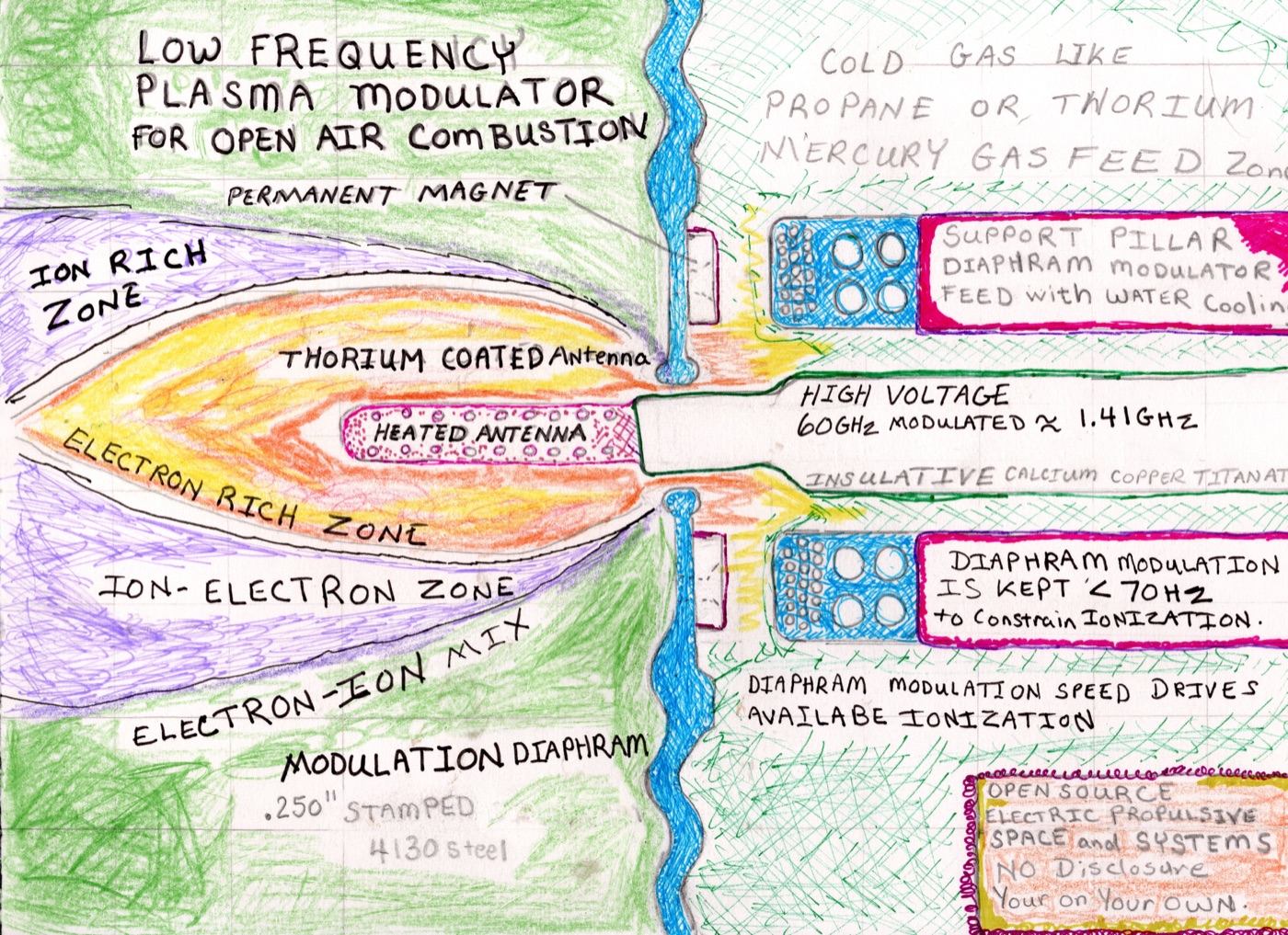
1 · Seed gasmercury + SF6 · propane · cesium
2 · Hot electron emitterheated thoriated filament or antenna
3 · High-voltage driveidle field · 20 kV at 300 kHz on the IPT
4 · GHz electron drive1 GHz+ magnetron · 60 GHz modulated ~1.41 GHz
5 · Slow mechanical modulatorpiston or diaphragm · under 70 Hz
“BUOYANCY SYSTEM PLASMA FIELD IGNITION SEQUENCE”
Typed page posted 2026-02-13 · the author's steps, shortened
- Echo-sound the surroundings“INITIAL PERMITIVITY ECHO SOUNDING of SURROUNDING MEDIA INTERFACE”
- Meter seed gas and hydrocarbon into both chambers“ION SEED GAS + HYDROCARBON GAS … precision metered”
- Release cold oxygen; oxygen and heated cesium near the exit“Cold O2 (< -170°F / -112°C) is released in small amounts”
- Heat the antennas“Incandescently antennas, mounted on pedestals”
- Switch on the transmitter“high Ghz Frequency High Voltage transmitter … ¼ wave Forward Sawtooth Pattern”
- Diaphragms start near 100 Hz, in phase“pumping in and out, in phase, like a set of lungs”
- Run them 180° out of phase“180° out of Phase, when in operation” … “once the bubble is stood up”
Energy routes the author names, and the test for each
From the author's posts, in date order
- 2024-12-25A hydrocarbon burned in the chamber; plates collect the currentfuel energy in vs output + heat
- 2025-03-02“shock it out of the Electrons Continuous Lattice”calorimeter on a shock-pulsed conductor
- 2025-03-27“Universal Thermal Background can be funneled”run sealed in a temperature-held enclosure
- 2025-05-05Seed “hot enough to full ionize cesium and bismuth”spectrometer + probe, output vs input
- 2025-09-08Budker's cycle posted as the theorypressure–volume loop vs heat in
- 2025-10-23Heated mercury “for over unity applications”reservoir heat in vs output
- 2026-01-14Mercury and helium in “Recipricating Alternators”piston work in vs electrical out
Budker's four-step cycle
G. I. Budker, published 1958 from work done in 1951: the paper the author posted as the theory of operation
- Expand: the plasma cools and pays energy into the circuit
- Shed some heat to a cold sink (here: the water jacket)
- Compress: costs less energy than step 1 gave back
- Reheat to the starting temperature: the heat source. In the paper it is a fusion reactor; for the IPT it is the route to identify and measure.
| Magnetic field squeezes | Piston squeezes |
| Solenoid windings collect | Screens and output stage |
| "Refrigerator" | Water jacket |
| Fusion reheats | Heat route to test |
Model prediction for an ideal cycle, 1 − (Vmin/Vmax)2/3; the measurement decides:
about 11% with the stroke drawn (1.18 : 1) · about 30% using all the room (1.7 : 1)
about 11% with the stroke drawn (1.18 : 1) · about 30% using all the room (1.7 : 1)
Three readings, kept apart
The author's material
- Sealed tube, mercury and SF6 seed, wire feed, water cooling
- Five recurring parts: seed gas, hot emitter, HV idle field, GHz electron drive, modulator under 70 Hz
- "Ignition" = seed gas lit into plasma ("full ionize cesium and bismuth")
- Screens = "collector of spaced currents"
- Goals: "amplifier", "massive arcs", "free energy"; lift for the vehicles
Ashton Forbes' reading: options to test
- Same as the sheet: screens do direct conversion; the piston sets the pressure
- Fusion core, or seeded-plasma converter
- Air-breathing like the vehicle siblings, or closed cycle like this sheet
- Magnetic piston, or the linear servo piston drawn
- Magnetic undulator, or collector screens
Making it work: the open engineering (the measurement decides)
- Measured: NASA cesium thermionic converters ran emitters near 2,000–2,100 K
- Measured: ionisation at 3.9 eV (cesium) and 7.3 eV (bismuth)
- Compression 1.18 : 1 drawn, 1.7 : 1 full travel; model predicts about 11% and 30%
- Model predicts 1 GHz reflects above 1.2 × 10¹⁰ cm⁻³; 60 GHz reaches denser plasma
- Model predicts electron resonance at 36 mT for 1 GHz with an added magnet
Build and measure the energy gain: meter every input, the electrical output and the water's heat over many hours. Log screen voltage and current against piston position; check "ignition" with a spectrometer and probe; for the vehicle, a capsule on a thrust balance in vacuum.
0:00 / 0:00